|
Explicit
|
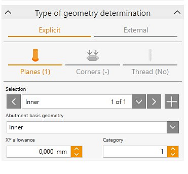
Specify machining areas for the interface geometry. Planes and categories are defined manually. The explicit definition of machining areas at implant interfaces is described in detail in the Defining Machining Areas at the Implant Interface section.
|
Planes
|
|
Definition of the ranges and categories of the interface geometry of the currently selected screw channel
|
|
Selection
|
Select plane via drop-down list or arrow keys
|
|
Inner
|
Inner geometry
|
|
Outer
|
Outer geometry
|
|
XY allowance
|
Lateral positive (positive value) or minus (negative value) allowance of the currently selected plane
|
|
Category
|
Categorization of the currently selected plane
|
Corners
|
|
Definition of corners for clearance in internal geometries. The definition of corners on interior geometries is described in more detail in the Defining Corners for Inner Geometries section.
|
|
Selection
|
Display and selection of corners
|
Thread
|
Thread selection. The process of adding threads to screw channels is described in more detail in the Defining Corners for Inner Geometries section.
|
|
Thread
|
Display and selection of the thread type
|
|
Offset thread begin
|
Displacement of the beginning of the thread.
|
|
Offset thread end
|
Displacement of the end of the thread.
|
|
|
|
|

|
External
|
|
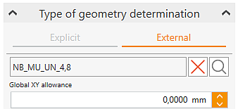
Load the interface geometry from a file. This allows you to open a model of an interface geometry (*.hdpartz) for which screw channels, planes, corners and/or threads have already been defined.
If metadata exist and the corresponding *.hdpartz libraries are referenced, these are loaded automatically.
|

|
Open
|
Open external interface geometry.
|

|
Delete
|
Delete external interface geometry.
|

|
Preview
|
Preview window for the external interface geometry.
|
|
Global XY allowance
|
Global lateral allowance for all planes defined at the interface geometry.
|
|
|
|
|
|
|
|

|
Positioning external interface geometries (*.hdpartz)
|
|
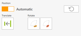
Automatic
|
Align external interface geometry to model with automated functions.
|

|
Move part to reference surface
|
Move external interface geometry in screw channel direction exactly to one plane of the model. Highlight planes one after the other with a mouse click.
|

|
Rotate part to selected point
|
Use the mouse to click a point on the interface geometry and on the model to be aligned with one another by rotating the interface geometry.
|

|
Rotate part to reference surface
|
Use the mouse to click a point on the interface geometry and a surface on the model to be aligned with one another by rotating the interface geometry.
|

|
Reset
|
Shifts are reset to restore the initial position.
|
|
|
|

|
Manual
|
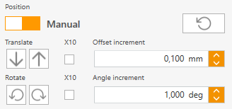
Manually align and rotate external interface geometry to implant interface geometry.
|
 
|
Translate
|
Move the part along the screw channel axis
using the set increment (offset) or 10 increments.
|
 
|
Rotate
|
Rotate part about the screw channel axis at one increment (angle) or 10 increments.
|
X10
|
10-fold increment
|
Activate multiple increment for translation or rotation.
|
|
Offset increment
|
0.01 to 10 mm
Increment in millimeters for displacement along the screw channel axis.
|
|
Angle increment
|
0.01 to 10°
Increment in degrees for rotation around the screw channel axis.
|
![]() Implant Interface
Implant Interface


