|
Generating layers
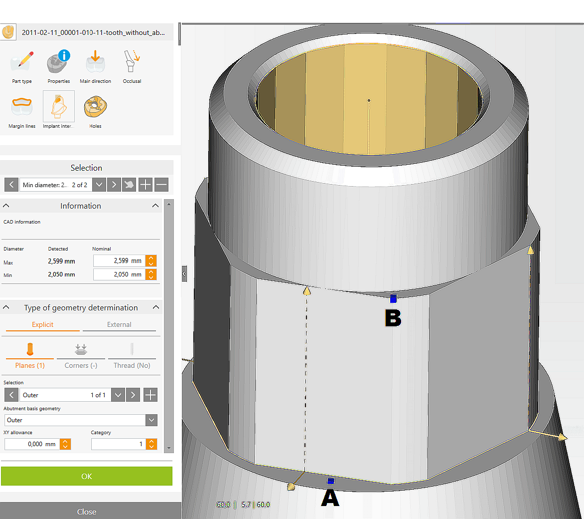
A machining area is defined by two points, with the first point (A) representing the beginning and the second point (B) representing the height of the area.
Select screw channel with mouse, drop-down list, or arrow keys.
Open "Type of geometry determination" drop-down list and select Explicit.
Left-click to define the plane (A).
The plane can be placed at any point between the abutment base line and the screw channel. At the height of the point set on the part, an intersection curve is inserted between an imaginary plane, which is orthogonal to the screw channel, and the part itself.
Left-click to define the height (B).
The point is generated at the nearest grid node.
The plane and its height are generated and displayed. The horizontal arrows indicate whether, according to the current definition, the area will be machined from the outside or from the inside.
The vertical arrows indicate the height at which the machining area was defined.
To delete a plane, select it with the mouse, drop-down list, or arrow keys and press Delete on the keyboard.
Editing plane properties
|


