|
Select the Set sintering pin button. Click on the part to generate the Sintering Pin.
|
Function window
|
|
|

|
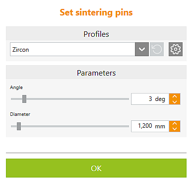
Profile
|
|

|
Select profile (template)
|
Select a preset profile from the drop-down list. Profiles must previously have been defined in the Support element profiles options.
|

|
Settings for profiles
|
Direct jump to the Support element profiles settings to define profiles for sintering pins.
|
Parameters
|
|
|
Angle
|
The set angle extends sintering pins from their highest point towards the part.
|
|
Diameter
|
Diameter of the sintering pin (at the highest point).
|
|
|
|
|
|
OK
|
Exit
|
|
|
|
|
|
|
|
|
Grafikfenster
|
|
|
|

|

|
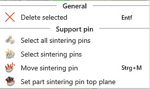
Select all sintering pins
|
With this button, all sintering pins currently set in the blank are automatically selected and can then be edited simultaneously, for example.
|

|
Select sintering pins
|
If one sintering pin of an object is selected, all remaining sintering pins of this object can then be automatically selected with this function and, for example, edited simultaneously.
|

|
Delete sintering pin
|
Delete selected
|

|
Move sintering pin
|
Holding the left mouse button down, move the sintering pin to the desired position. Alternatively, double-click the sintering pin to start the mode.
|

|
Set part sintering pin top plane
|
Using the mouse, drag the boundary area to the desired position. In particular when working with concave blank surfaces, we recommend that you define a sintering pin top plane for one or more parts.
|
![]() Setting Sintering Pins
Setting Sintering Pins


