Icon is displayed.
The type of margin line must be compatible with the part type. If it is not, calculation is not possible for safety reasons.
|
|
|
Adding a margin line
|
|

|
|
|
|
|
|
|
|
|
|
|
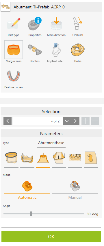
Select the margin line type
|
|

|
Coping
|
Click within the bounding area:
The crown edge (margin line) is determined and colored blue.
|

|
Inlay/Onlay
|
Click within the bounding area:
The crown edge (margin line) is determined and colored green.
|

|
Abutment base
|
Click the corresponding edge:
The margin line is determined and colored pink.
|

|
Emergence curve
|
Click the corresponding edge:
The margin line is determined and colored green.
|

|
Tooth pocket
|
Click within the bounding area:
The margin line is determined and colored violet.
|

|
User-defined area
|
The options for defining custom areas are described in the User-Defined Areas section in more detail.
|
Mode for determining the margin line
|

|
Automatic
|
Determine margin line automatically. Click within the bounding area or the corresponding edge.
|

|
Manual
|
Manually define the area. Click the edge of the desired boundary to set the starting point. Follow the edge with the mouse pointer. Press the “Backspace” key to delete the last point. Hold down the “Ctrl” key to interrupt automatic edge detection.
|
Angle
|
|
|
|
Angle setting for automatic detection
|
Angular range between facets to determine the boundary. If the margin line is not recognized automatically, adjust the angle to a value such as 5 or 15 degrees.
|
Category
|
Choose category
|
.. 0 ... 9 ... n
This number is used to activate the machining steps associated with the corresponding number from the template.
|
|
Editing existing margin lines
|

|
  

|
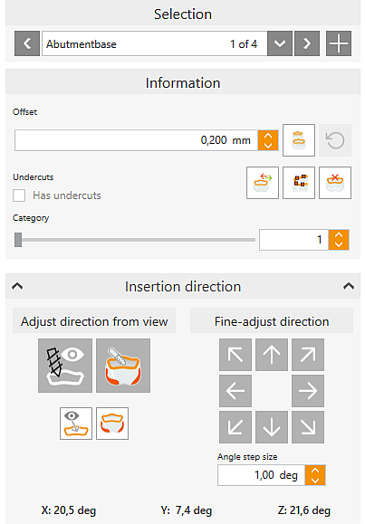
Selection
|
To edit existing margin lines, select the corresponding curve using the left/right keys or via the drop-down list.
If a margin line is selected, a new margin line can be added directly with the + button.
|
Offset
|
|
Offset value to move the margin line inwards/outwards.
Positive values -> inwards
Negative values -> outwards
|

|
Move
|
Move the margin line inwards/outwards by the offset value.
|

|
Previous
|
Undo last move.
|

|
Change the type of margin line
|
E. g., from coping to inlay/onlay if the existing setting is to be changed.
|

|
Edit margin line
|
•Left-click and hold the mouse button to move points. •Add new points by clicking between two existing points. •Delete points with middle mouse button or move to free space. |

|
Delete margin line
|
Delete the selected margin line.
|
Undercuts
|
Set undercut property for 3+1- and 3+2-axis machining. It is possible to edit undercut areas.
|
|
Has undercuts
|
Differentiation possible by performing a conditional calculation.
Depending on the setting in the template, different machining methods can be enabled for this margin line depending on the status.
|
|
|
Insertion direction
|
|

|
Alignment to view
|
Define the current viewing direction of the part as the insertion direction (=machining direction).
|

|
Adjust direction by undercut minimization
|
An insertion direction optimized for undercuts is calculated and set.
|

|
Rotate view to insertion direction
|
Rotate the view to the insertion direction of the selected margin line.
|

|
Calculate undercuts in check direction
|
Undercut areas are calculated from the direction of insertion and displayed in red.
|
|
Angle step size
|
Set the size of the angle steps for “Fine-adjust direction” in degrees.
|
 
|
Fine-adjust direction
|
Set the insertion direction using the arrow keys.
|
X; Y; Z
|
Current direction
|
Current angles of the insertion direction of the margin line, orthogonal to the blank.
|
![]() Margin Lines
Margin Lines


