Select part and click the Set connectors button.
|
|

|
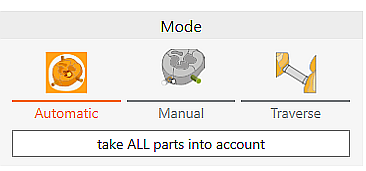
Modus
|
|

|
Automatic
|
Automatically set connectors from profiles. Perform connector calculation for all parts with "take ALL parts into account"
|

|
Manual
|
Default method:
Move the mouse over the point where a connector is to be added. A circle is projected onto the part, which serves as a preview of the docking point. By clicking the left mouse button the connector is generated.
New alternative method (must be activated in the general settings):
Select the view blank from above (top) and click approximately in the area where the connector should be placed. When generating the connector, the parameters in the function window are automatically taken into account.
|

|
Traverse
|
Place a traverse between two objects. Click on the first object, move the straight line to the second object and click again with the left mouse button.
|

|
Graphics window
|
|

|
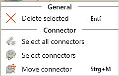
Select all connectors
|
With this button, all connectors currently set in the blank are automatically selected and, for example, can then be edited simultaneously.
|

|
Select connectors
|
If a connector of a part is selected, this function can be used to automatically select all remaining connectors of this part and, for example, edit them simultaneously.
|

|
Delete connector
|
Icon becomes active after at least one connector has been selected. All selected connectors are deleted.
|

|
Move connector
|
To move, highlight connector and click the icon. You can also double-click it.
|
|
|
|
Use part type-specific connector profiles
|

|
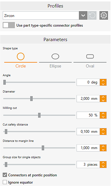
Profile
|
|

|
|
Select profile (template)
|

|
|
Settings for profiles
|

|
|
Use part type-specific connector profiles (on)
|

|
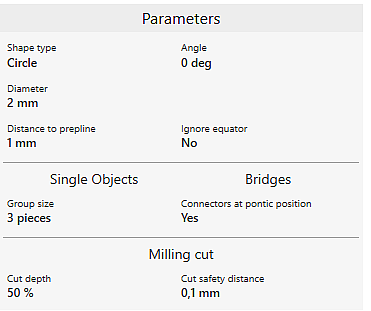
Parameter
|
Display of the default parameters of the selected connector profile.
|
Without using part type-specific connector profiles
|

|

|
Without using part type-specific connector profiles (off)
|
The part type-specific parameters of the selected profile are not applied when generating the connectors.
|
Parameter
|
|
The parameters from the selected connector profile are displayed
|
Shape type
|
Circle
Ellipse
Oval
|
Three different basic shapes are available.
|
|
Angle
|
The angle that can be set here opens from the part towards the milling range limit.
|
|
Diameter
|
Diameter of the connector with circle shape.
For ellipse and oval, two sliders for height and width are displayed instead of the diameter.
|
|
Milling cut
|
Indicates the percentage of the original diameter remaining when cutting/reducing connectors. For ellipse and oval this value is related to the height. From a value of 99% on, the connector is cut completely.
|
|
Cut safety distance
|
Safety distance to the part, which is maintained when using the 3D curve milling strategy to reduce connectors.
|
|
Distance to margin line
|
Value by which the connectors are set above margin lines.
|
|
Group size for single objects
|
Number of connectors, which are set for single elements.
|
|
Connectors at pontic position
|
Setting whether connectors should be set for pontics which were created either manually or by information from metadata.
|
|
Ignore equator
|
Determines whether the equator should be ignored as docking point for connectors if there is an boundary line in undercut below the equator.
|
![]() Set Connectors
Set Connectors


