|
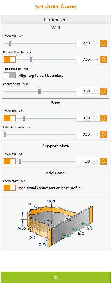
Select the part and click the Set sintering frame button.
Click the part to generate the sintering frame. Edit it by adjusting the parameters and clicking the part again.
By combining the different possibilities, different types of sintering frames can be generated.
|
Funktionsfenster
|
|
|

|
|
|
|
|
Wall
|
|
Thickness
|
Wall thickness/thickness of the sinter frame.
|
Reduced height
|
The height of the sinter frame can be reduced to the highest and lowest connector.
|
Top boundary
|
Align top to part boundary.
|
Center offset
|
Use this function to move the height-reduced portion of the frame orthogonal to the blank. Independent of this, the rule applies here as well: Upper and lower limits of the reduction are determined by the highest and lowest connector.
|
Base
|
|
Thickness
|
Wall thickness/thickness of base.
|
Extended width
|
The sinter frame is extended at both ends by the set value.
|
|
|
Support plate
|
|
Thickness
|
Wall thickness / thickness of the support plate.
|
Additional
|
|
Additional connectors on base profile
|
To stabilize a part, additional connectors can be attached to the base. The graphic representation is symbolic and does not correspond to the result.
The thickness and the distance between the connectors are defined in the Cut Sinter Frame job.
|
Graphic
|
The graphic below the parameters always shows only the currently activated options.
|
|
|
|
|
|
|
|
|
|
|
OK
|
Exit
|
|
|
|
Grafikfenster
|
|
|

|

|
Delete sinter frame.
|

|
Change the side of the sinter frame. Alternatively double-click on frame.
|
![]() Setting Sintering Frames
Setting Sintering Frames


