|
Function for producing an internal thread by thread milling with thread whirling tools.
The prerequisite for this is an existing screw channel or hole where the thread is defined.
The threads comply with ISO and UNF standards up to approx. 4 mm.
Before thread milling, the core hole diameter in the screw channel or hole must already have been cleared out by drilling or milling.
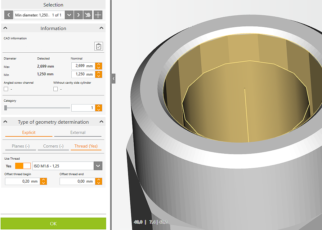
The core hole diameter is displayed in the selection window for the thread types and in the information of the screw channel under min.
|

|
Defining threads
Select screw channel with mouse, drop-down list, or arrow keys.
Open "Type of geometry determination" drop-down list and select Thread.
Enable the Thread switch to assign a thread.
Select thread in the drop-down list.
In the Offset thread begin input field, you can adjust the starting point of the thread in the direction of the occlusal side.
In the Offset thread end input field, you can adjust the end point of the thread in the direction of the cavity side.
To delete a thread, disable it using the Thread switch.
|

|
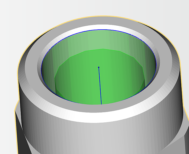
If a thread has been assigned to a screw channel or hole,
this is indicated by a green channel.
|
|
|
|
|
|
|
|
|
Thread types
The available thread types are shown in the selection window.
▪ISO (metric) Thread diameter – core hole diameter Type Thread Ø / core hole Ø
ISO M 1 / 0.75
ISO M 1.1 / 0.85
ISO M 1.2 / 0.95
ISO M 1.4 / 1.1
ISO M 1.6 / 1.25
ISO M 1.7 / 1.3
ISO M 1.8 / 1.45
ISO M 2 / 1.6
ISO M 2.3 / 1.9
ISO M 2.5 / 2.05
ISO M 2.6 / 2.1
ISO M 3 / 2.5
ISO M 4 / 3.3
▪UNF Thread identifier / core hole diameter & Identifier / core hole Ø
0 / 80 UNF / 1.25
1 / 72 UNF / 1.55
2 / 64 UNF / 1.9
3 / 56 UNF / 2.15
4 / 48 UNF / 2.4
5 / 44 UNF / 2.7
6 / 40 UNF / 2.95
8 / 36 UNF / 3.5
Further details on threads are available at
http://www.gewinde-normen.de
|


