|
Settings for the machine and fixtures
|
Configuring the machine

|
The machine determines the process for calculating the toolpaths. In hyperDENT you can configure machines in such a way that axis limitations are already checked by the application during calculation.
You can set different combinations of the rotation axes for this process:
|
|
▪Pure table kinematics
All rotation axes are in the table (e.g., C-table on A-bridge). |
|
▪Pure head kinematics
All rotary axes are in the head. |
|
▪Mixed kinematics
One rotary axis is in the table and the other rotary axis is in the head. |
Primary and secondary axis
|
In order to set the correct axis, you must determine the primary and secondary axis:
|
|
▪Pure table kinematics and pure head kinematics
The primary axis is always the axis which “takes along” the other axis when there is a rotation. Therefore, whenever the primary axis is rotated, the alignment of the secondary axis always changes too. |
|
▪Mixed kinematics
The primary axis is always the table axis.
The secondary axis is the head axis. |
|
▪You can select A (rotation around X), B (rotation around Y), or
C (rotation around Z). |
|
▪Depending on the choice of the primary axis, the following are available for the secondary axis:
A or C (primary = B), B or C (primary = A), or A or B (primary = C). |
|
▪The direction of rotation for the axes is always indicated in a mathematically positive sense, i.e., counterclockwise. |
|
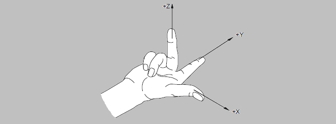
▪The designation of the axes corresponds to the “right-hand rule.” |
Right-hand rule

|
The thumb, index finger, and middle finger of your right hand define the coordinate system.
|
Direction of rotation

|
The mathematically positive direction of rotation is obtained by (hypothetically) placing your hand around the desired axis so that your thumb points in the positive direction of the axis. Your other fingers indicate the positive direction of rotation.
|
Relative tool movement
|
There are various ways of defining the rotational directions of the axes in the context of machining. However, the perspective usually coincides with the movement the tool performs in relation to the part.
|
Example of rotational directions in hyperDENT
Rotational directions that are identified in hyperDENT as positive or negative.
Example 1 Rotation around X (= red axis) in positive direction
|

|
Example 2 Rotation around Y (= green axis) in positive direction
When you define the parameters for the rotational directions in the menu, it is thus important to take into account the rotational directions (mathematically positive) specified by hyperDENT.
|

|
Example 3 Variant rotational direction
▪The machine does not rotate in the mathematically positive sense, but against the mathematically positive sense. ▪The machine has a swiveling range of -10 to +120 in the A-axis.
Since the rotational directions of the machine do not match the directions of hyperDENT, the signs must be inverted:
This means the minimum angle is -120 and the maximum angle is +10.
|
|
![]() Machining...
Machining...


