|
The general settings apply to all jobs in the template.
Margin line thickness
|
Minimum thickness of edge of cap (margin line), that machining will not go below.
If the part is thicker at the margin line, the geometry of the coping margin remains unchanged.
If the margin line is made thicker, it may also be necessary to extend the milling boundary.
|

|
Milling boundary
|
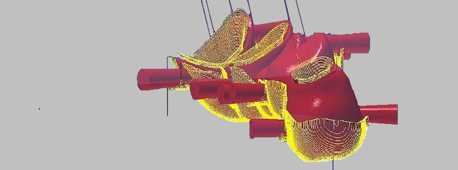
When producing the dental restoration, the tool must be able to machine all areas of the part. In order to do so, the material must be removed in a sufficiently large area – the milling area – around the part.
|
The width of the milling area is dependent on the tool diameter and inclination when performing a machining operation with a coping-specific tilt. The milling area must be large enough for the current machining operation; if it is not, you need to extend the milling boundary.
|
The milling boundary lowers the risk of collision between the tool and the fixture, reduces the machining time, and enables multiple parts to be placed on one blank (e.g., a disc).
|
Bounding strategy
|
Offset
|
Machining (roughing) only within a defined boundary.
Auxiliary geometries (milling boundary 1 around the part) are generated in accordance with a blank that is to be equipped with several parts (e.g., disc).

|
Fixture
|
Some special fixtures/blank geometries require auxiliary geometries to be created in such a way that the part can be accessed from all sides during machining. Required setting for processing in sections. Connectors are set in the correct orientation for each holder.

|
Boundary offset
|
Width of the milling boundary around the part. It depends on the milling diameter used and the inclination for a machining process with a coping-specific tilt.
Calculation:
Diameter of the roughing cutter + approx. 0.7 mm. If the margin line is made thicker, it may also be necessary to extend the milling boundary.
|
Min. distance: Part – Fixture
|
Corresponds to the offset milling boundary; defines the limit to the fixture. Depends on the cutter diameter.
Calculation:
Diameter of the roughing cutter + approx. 0.3 mm.
|
Boundary angle
|
Angle of the milling boundary that is orthogonal to the blank surface. Important for protecting the tool in the case of material that is difficult to cut.
|
Boundary angle 2
|
Angle for the milling boundary that is used once a certain blank thickness is reached.
|
Blankthickness bigger for boundary angle 2
|
Once the specified blank thickness is reached, the angle for the second milling boundary is used.
|
Startheight of opening angle
|
|
Bottom of equator
Bottom of part
|
Default for machining with a milling boundary. The start height of the milling boundary’s opening angle corresponds with the lowest point of the equator (1) of the part.
For better access, you can set the start height deeper onto the lowest point (2) of the part (+ offset). This will extend the milling boundary.

|
Offset height
|
Offset for the start height of the opening angle across the bottom of the part.
|
Outer machining ortho to blank
|
Yes
|
Roughing also takes place when the main machining direction is tilted (height optimization) orthogonally to the blank.
|
No
|
Tilted machining; all milling planes are tilted toward the blank surface.
|
|

|
Coolant
1 / 0
2 / 1 + 2
3 / 1 + 3 / 2 + 3
4 / 1 + 4 / 2 + 4 / 3 + 4
|
Cooling lubricant on (1) / off (0)
Other variants for controlling the cooling lubricant make it possible to perform more complex processes, e.g., automation or ultrasonic machining. You have the option of setting the cooling lubricant globally or separately for each job. Follow the instructions of the machine manufacturer!
|
Tool reference
|
|
Center/Tip
|
Machine-specific details for calculating the toolpath based on the center/tip of the tool.
|
Clearance above blank
|
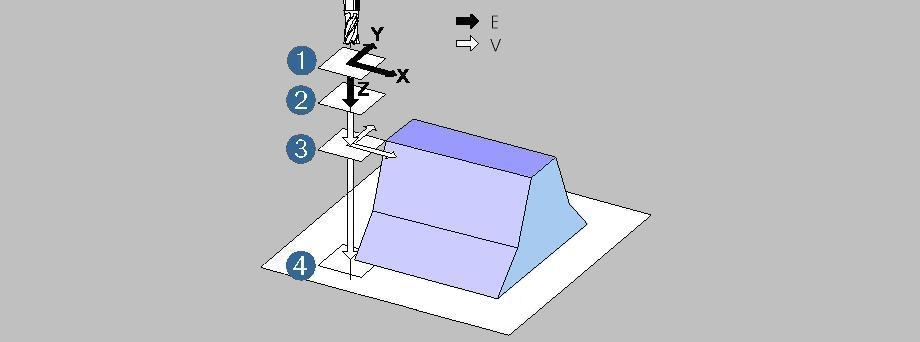
Safety distance (1) above the blank; for rapid traverse movements in all 3 axes. The distance refers to the Z axis of the current milling operation (frame).

1) Clearance level
2) Clearance distance
3) Top of blank
4) Bottom of blank
|
Clearance distance
|
Clearance distance (2) above the part for the depth setting on the Z-axis: above for rapid traverse, below for Z-feedrate.
|
Check fixture against collisions in 3X Jobs
|
|
Yes/No
|
Enable/disable collision check for the fixture for 3X machining jobs. Calculation of toolpaths with collision check results in longer calculation times.
|
Check fixture against collisions in 5X Jobs
|
|
Yes/No
|
Enable/disable collision check for the fixture for 5X machining jobs. Calculation of toolpaths with collision check results in longer calculation times.
|
Fixture allowance
|
Global holder allowance for roughing operations.
|
Reduce factor
|
Factor for reducing the STL facets to speed up the calculation time. The factor refers to the machining tolerance:
|
0 =
|
no reduction
|
1 =
|
reduction equal to the machining tolerance
|
Split model
|
|
Yes
|
Separate STL data is produced for 3D jobs with no facets in the undercut areas. This helps to reduce the calculation time.
|
No
|
STL facets are transferred completely to the cycle.
|
Max. angle increment in 5X jobs
|
Machine-specific value that limits the changes to the tool tilt that can be made between two points. The maximum G1 length and the value for the maximum angle increment depend on the control unit (RTCP) and machine. Observe the information of the machine manufacturer!
|
Comment
|
Entry of comments that are written to the NC info file and in some cases to the NC header (e.g., for Datron D5).
|
Segment-wise (section-wise) machining
|
When processing rod-shaped raw materials, it can be helpful to machine the part section by section.
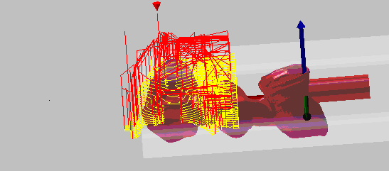
This machining mode can be enabled or disabled separately for each job via the parameters for all roughing, finishing, and rest machining jobs. It allows you, for example, to completely machine the cavity side first, followed by segment-wise machining of the occlusal side. During machining, the occlusal side is divided into individual sections, and each section is always processed fully before the process moves on to the next section.
There is an additional offset value for roughing jobs with the roughing mill.
You need to configure the [General settings] > [Bounding strategy] > [Fixture] parameter for the template.
|
Caution! Risk of collision! The blank is not included in the collision check.
|

|
Min. segment distance to element boundary
|
Minimum distance of the machining section to the element boundaries, e.g., boundary lines of the margin line, emergence profile, and abutment base.
|
Min. segment width
|
Minimum width of the machining section.
|
|
|
Consistency check
In order to be able to react to various production methods, the consistency check was integrated into the general
template settings.
These can be taken from the general settings or adapted to specific templates.
|
|
|
Arc curve mandatory
|
|
On
|
An error message is displayed if no arch curve has been defined on the part.
For segmented machining startegies in "Overall finishing occlusal side (bridge)".
|
Off
|
No error message is output if no arch curve has been defined on the part.
|
|
|
Occlusal direction mandatory
|
|
On
|
An error message is displayed if the metadata does not contain information about an occlusal insertion direction and this direction has not been set manually.
e.g. for abutments
|
Off
|
No error message is displayed if the metadata contains information about an occlusal insertion direction or if it was set manually.
|
|
|
|
|
|


