|
The geometry describes the shape of the blank:
|
▪Disc |
Disc shape
|
|
▪Cylinder |
Cylinder shape
|
|
▪Box |
Box shape
|
|
▪Extrusion |
Blanks of any shape described by a closed contour and defined by specifying a height.
|
|
▪Freeform |
Blanks of any shape that are described by a model file (closed STL model).
|
|
Prefabricated blanks (prefabs)
|
Prefabricated blanks of any shape with finished screw channel, screw seat, and interface geometry described by a model file (closed STL model).
|
|

|
|
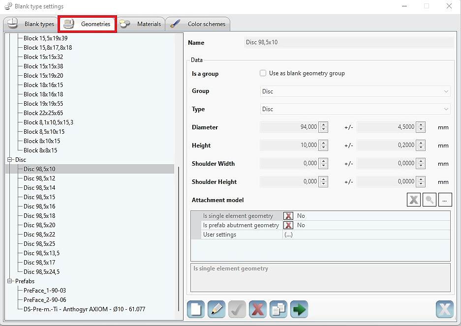
1) In the [Settings] menu, call up the [Blanks] > [Blank types…] menu item.
2) Click the [Geometries] tab.
3) Create, edit, use, delete, copy new geometry.
|
|
Name
|
Freely selectable name for the shape of the blank.
Preferably assign a name with reference to the shape, e.g., “disc100-14” for a disc of diameter 100 mm and a height of 14 mm.
|
|
Type
|
Selection field for the shape of the blank:
Disc, cylinder, box, extrusion, freeform.
|
|
Diameter
|
Diameter of the blank
|
|
Height
|
Height of the blank
|
|
Width
|
Width of the blank
|
|
Depth
|
Depth of the blank
|
|
+/-
|
Tolerance, production-related deviation of the blank from the specified value for diameter, height, width, depth.
The blank value is taken into account when placing the parts, while the tolerance value is also taken into account for calculating milling paths,
e. g.: 14 mm + 0.2 mm = 14.2 mm.
|
|
Extrusion curve
|
Call up the selection window to select and open the file that contains geometry data.
|
|
Freeform model
|
Call up the selection window to select and open the file that contains geometry data.
The freeform model must be available as an *.STL file.
|
|
Attachment model
|
Call up the selection window to select and open the file that contains geometry data.
Attachment models securely attached to blank geometries that are to be included in the collision check.
The attachment models are subject to the same transformations as the blank geometry (rotation of blanks) and are displayed in hyperDENT as part of the holder geometry.
The attachment model must exist as an *.STL file.
|
|
Is single element geometry
|
Yes
A single-element geometry is used for the production of single elements such as preform abutments and hybrid ceramic blocks. To use the filter options for blank management, set this parameter to “Yes.”
|
|
|
|
Is prefab abutment geometry
|
Call up the submenu and specify the insertion point for the part if the interface geometry has already been machined: --> “Prefabricated blanks – Prefab.”
The freeform model with the connection geometry must be available as an *.STL file.
|
|
Zero point
|
Calls the submenu for specifying the position of the zero point for inserting the part.
|
|
Screw channel axis
|
Calls the submenu for specifying the position of the screw channel axis for inserting the part.
|
|
X-axis
|
Calls the submenu for specifying the position of the
X-axis for inserting the part.
|
|
Hole diameter
|
Diameter of the screw channel.
|
|
Alias settings
|
Calls the submenu where you can make further settings for the mapping function of the defined interface for inserting the part.
Display, add, delete settings.
|
|
Name
|
Name of the alias setting.
|
|
Rotation
|
Angle of rotation about the screw channel axis.
|
|
Offset
|
Default value for the displacement along the screw channel axis.
|
Geometry groups
The geometry groups were introduced with the aim of arranging blanks into groups e.g. by prefabs manufacturer, which can be clamped into a common fixture.
|

Each created geometry can be used as a geometry group. For this purpose, the checkmark in "Use a blank geometry group" must be set in Geometries > Data.

This allows the geometry groups to be selected in all previous setting and filtering options for geometries (Project Manager, Stock Loading Dialog, Milling Strategies, Holding Elements,...).
▪The freeform model and the attachment model must be available as an *.STL file. ▪The coordinate systems of the fixture, part, and attachment model must have the same alignment. ▪The coordinate systems of the prefabricated blank, fixture, and part must have the same alignment.

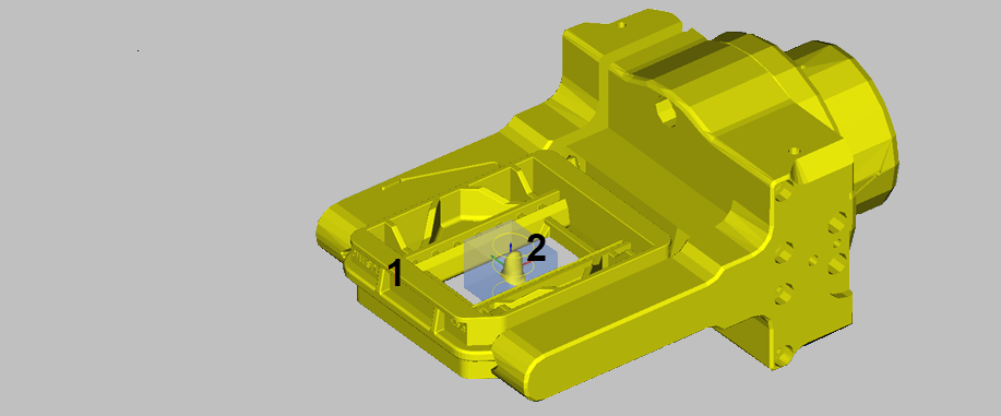
The attachment model can also be used with other blank shapes, for example, to create a frame (1) around the blank (2).
|


